
BioShieldUV® Magnetic (SL) Series Complete Installation Guide
Models covered: SL18 WallPlug | SL36 WallPlug | SL18-HVAC | SL36-HVAC
Before You Begin: HVAC models must be installed by a licensed HVAC technician or electrical contractor. Installation by anyone other than a qualified professional voids the warranty. All installations must comply with applicable national and local building codes. Read all safety warnings in full before handling any components.
Quick Start options
Watch Installation Video:

Need help with your particular HVAC System?
Find a certified installer in our professional directory.
Safety Instructions
Read every safety section below before touching any component. These warnings apply to all models and all installation environments.

UV Germicidal Lamp Safety
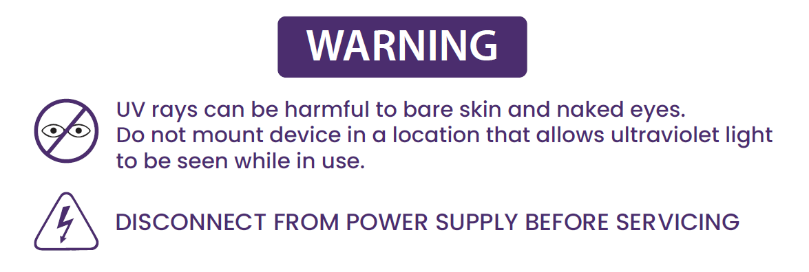
This luminaire is designed for use with germicidal lamps and must be installed per the provided instructions to prevent exposure of eyes and bare skin to harmful UV radiation.
Electrical Safety
Always turn off the main power switch before plugging in or performing any maintenance on the unit.
Lamp Handling
Handle the UV lamp with gloves at all times. Oils from bare hands reduce UV output and cannot be reversed by cleaning.
If the lamp glass is touched without gloves, wipe the affected area with isopropyl alcohol before powering the unit on.
Broken Lamp Hazard
Never touch a broken UV lamp with bare hands.
UV lamps contain a small amount of mercury and may be harmful to skin and eyes if released. If mercury contacts skin, wash the area immediately with mild soap and water and seek medical attention if necessary. Carefully collect broken pieces and dispose of them in accordance with local environmental regulations.
UV Material Exposure
UV-C light travels in a straight line and will degrade certain materials that fall within its direct path over time. Plastic drain pans, flex duct liner, foam insulation, filter media, and exposed wiring are all susceptible.
Before installing, shield any vulnerable materials with aluminum foil tape. Metal ductwork and components are unaffected.
Location Restrictions
Improper installation, adjustment, alteration, service, or maintenance can result in fire or electrical shock.
This unit is rated for dry locations only and must be installed exclusively in supply or return ductwork. It is not intended for supplemental heating applications and must not be installed in ductwork where supply air temperature regularly exceeds 105°C (221°F).
What is in the Box
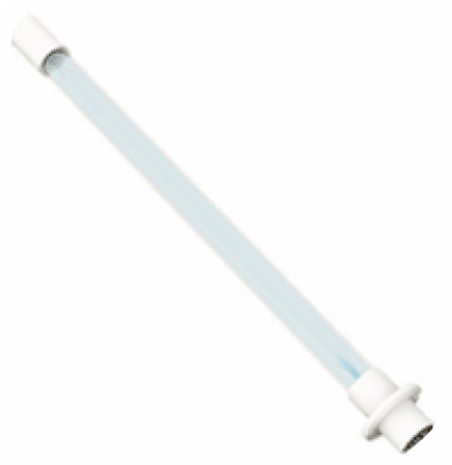
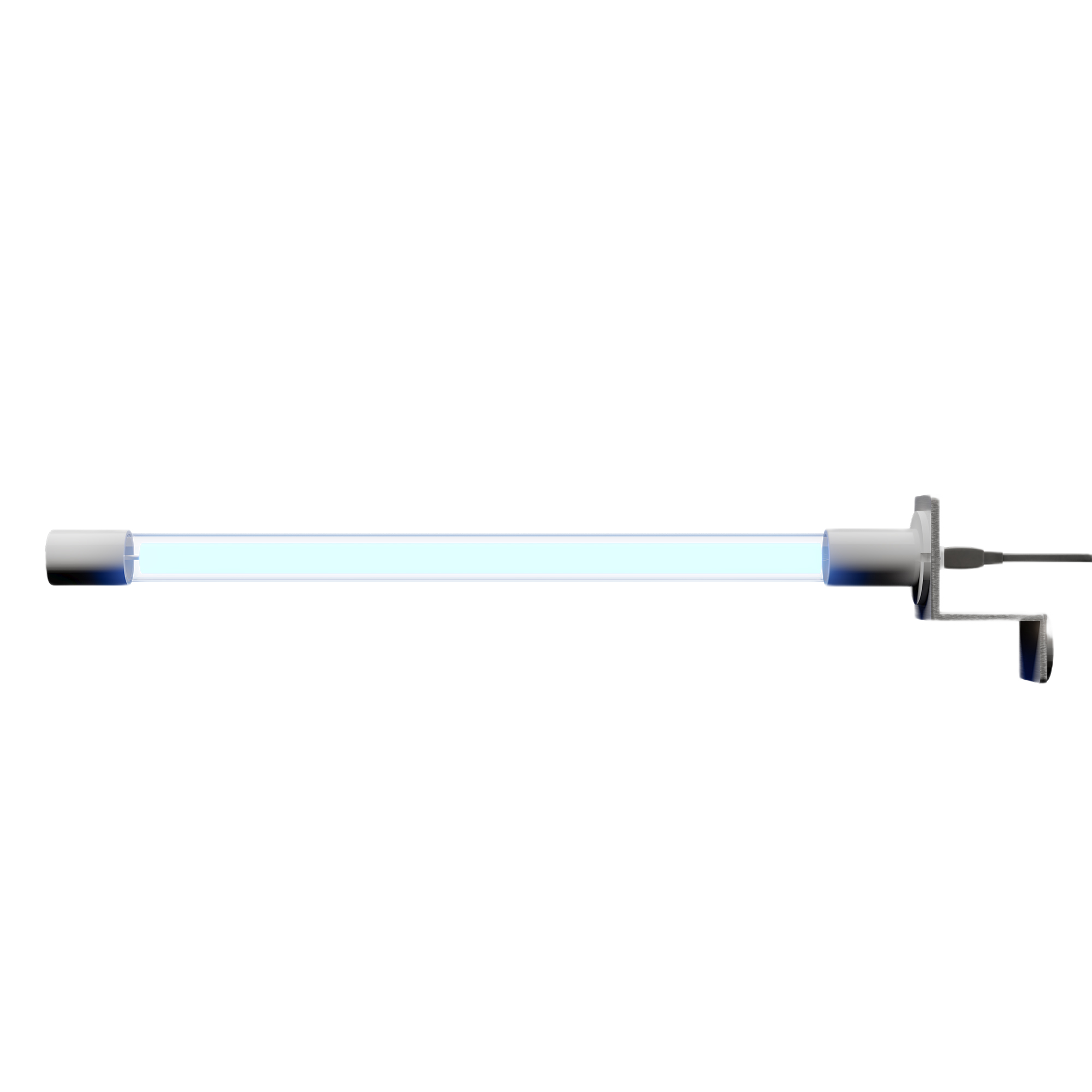
TruBlu™ UV-C Lamp
Germicidal UV-C bulb

Magnetic Holder
Steel mounting bracket with lamp holder
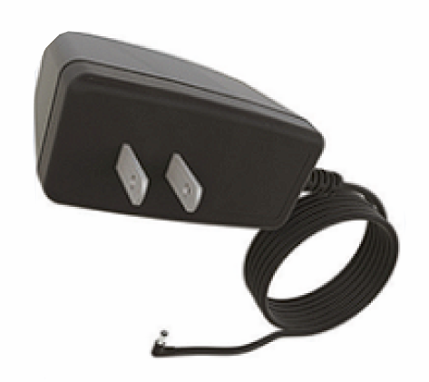
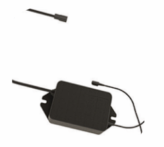
Power Supply
Wall adapter (WallPlug) or external ballast (HVAC)
Lamp Cable
4-pin keyed connector cable
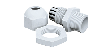
Cable Gland
Threaded strain relief for duct wall (1" hole)
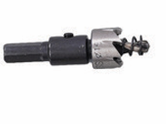
Step Drill Bit
Creates 1" cable hole (all models) & ½" sight glass hole (HVAC)

Warning Sticker
ETL compliance sticker & drill guide
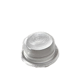
Viewport
Pressed into ½" hole to view lamp
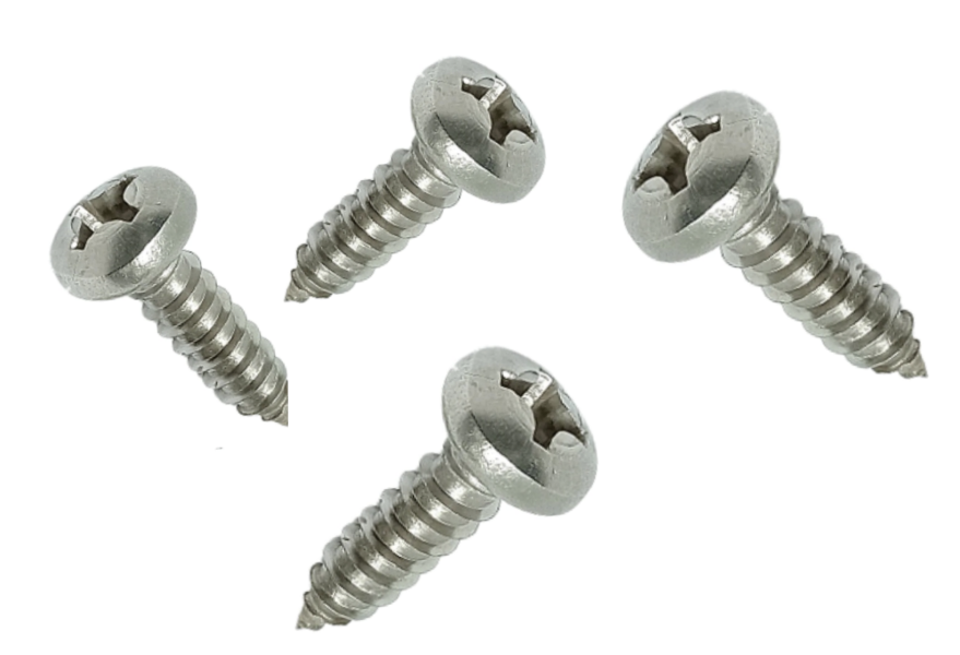
Self-Tapping Screws ×4
Non-magnetic surface mount & ballast mounting
Non-Magnetic Surface Alternative
If the mounting surface is non-ferrous or the magnetic hold is not sufficient, snap the mounting bracket apart by bending it at the joint, remove the magnet, and attach the bracket directly to the duct wall using the included self-tapping screws [I]. Seal any insulation that was disturbed with aluminum foil tape to prevent air leakage.

Part 1: Magnetic Bracket and Lamp Installation
Find a Suitable Location
Open the Air Handler Cabinet
- Select a mounting location on the interior back or side panel
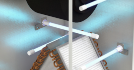
- Ensure the lamp has a clear, direct line of sight to the evaporator coil
- Position the lamp 12 to 14 inches from the coil
- Aim the lamp directly at the coil for optimal performance
| System Type | Recommended Placement |
|---|---|
| Upflow (furnace below, coil above) | Return side of the air handler for direct coil cavity access |
| Downflow (furnace above, coil below) | Supply side of the air handler |
| Horizontal system | Either side of the air handler with unobstructed line-of-sight to the coil face |
| Heat pump (no furnace) | Inside the air handler cabinet, aimed directly at the coil |
Clearance and Surface Requirements
The lamp assembly must fit completely inside the duct cabinet. Make sure there is 18 to 23 inches of open space in the direction the lamp will extend.
The magnetic bracket [B] will only stick to steel. Test the surface with a household magnet before choosing the location. If the magnet does not stick, use the screw-mount method described in Step 4.
Placement Tips
Position the lamp to cover the drain pan in addition to the coil face as the drain pan is one of the most common sites for mold accumulation. Avoid pointing the lamp directly at filter media, as UV-C degrades filter materials with sustained exposure. Do not install downstream of a humidifier.
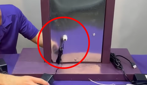
Attach the UV Lamp to the Magnetic Bracket
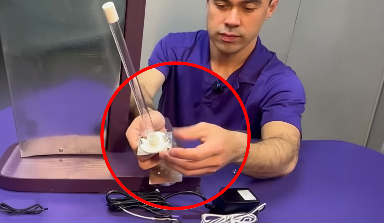
With gloves on, pass the lamp base [A] through the opening in the magnetic mounting bracket [B] and fasten it using the included quick nuts. The lamp should seat firmly against the bracket with no visible gaps.
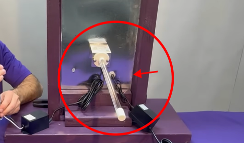
Connect the 4-Pin Lamp Cable
Connect the lamp cable [D] to the 4-pin connector on the UV lamp [A]. Align the keyed tabs on the connector with the corresponding slots on the lamp, then press firmly until you feel a definitive click.
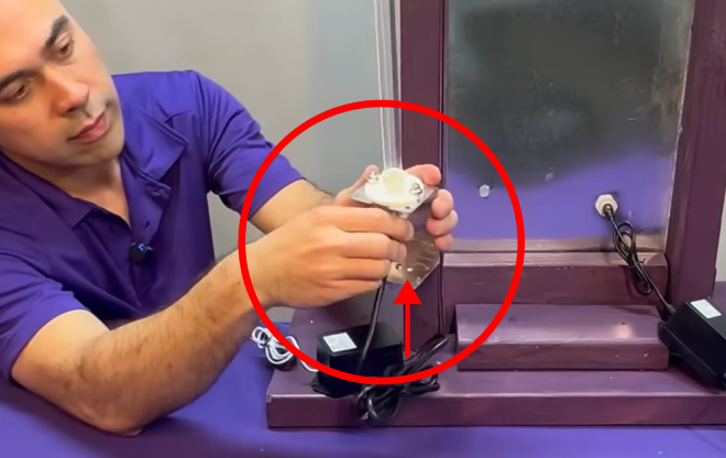
Position the Magnetic Bracket
Hold the magnetic base [B] against the chosen steel surface inside the air handler and allow it to snap into position. Confirm the lamp is angled correctly toward the coil before routing the cable. The magnet allows you to reposition the bracket freely at this stage, so take the time to confirm placement before moving on.
Part 2: Wiring Installation
Confirm your model before proceeding as wiring differs between WallPlug and HVAC models.
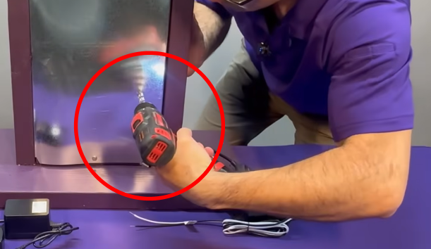
Drill the Cable Exit Hole
Using the included step drill bit [F], drill a 1" hole through the air handler cabinet wall.
- Position the hole as low as practical
- Choose a location that allows clean cable routing
- For WallPlug models, drill near an accessible outlet
Install the Cable Gland
Insert the cable gland [E] into the hole from the outside of the cabinet.
Thread the locknut from the inside and tighten until secure.
Route the Cable
Feed the appropriate cable through the gland into the cabinet:
- WallPlug models: Route the power cord from the wall adapter [C]
- HVAC models: Route the lamp cable [D]
Leave enough slack inside for a relaxed connection.
Tighten the gland nut finger-tight to secure the cable and seal the opening.
Model-Specific Power Connection

WallPlug Models
- Inside the cabinet, connect the wall adapter [C] to the lamp cable [D]. Align the square connectors and press firmly until the latch clicks.
- Ensure connections are dry and positioned away from any condensate drip paths.
- Plug the wall adapter into a nearby outlet.
Pour éviter les chocs électriques, introduire la lame la plus large de la fiche dans la fente la plus large.

HVAC Models
- Mount the external ballast [C] to the exterior of the duct using the included self-tapping screws [I].
- Connect the ballast to a dedicated 24VAC transformer using the tap-in connectors [J].
- Connect the ballast output to the lamp cable [D] through the cable gland.
Pour éviter les chocs électriques, introduire la lame la plus large de la fiche dans la fente la plus large.
Part 3: Monitoring Lamp Operation from Outside the Duct
WallPlug models use the built-in LED on the power adapter to confirm lamp status where blue means operating, red means service is needed.
The warning sticker and sight glass lens give HVAC installers and homeowners a way to confirm lamp operation from the exterior of the duct without opening the cabinet. Install both components before closing up the system.
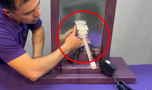
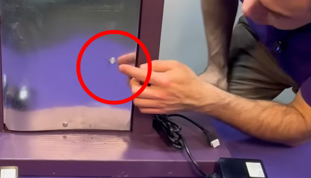
Apply the Warning Sticker
Select a location on the exterior duct wall that corresponds to the area directly behind or beside the installed lamp. Clean and dry the surface, then press the warning sticker [G] firmly into place. The printed circle at the centre of the sticker serves as the drill guide for the next step.
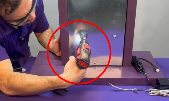
Drill the Sight Glass Hole
Using the included step drill bit [F], drill a 1/2" hole through the centre of the printed circle on the sticker and through the duct wall below it.
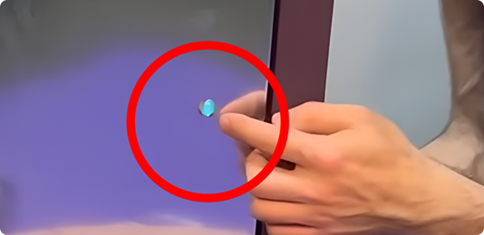
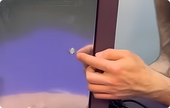
Install the Sight Glass Lens
Press the sight glass lens [H] firmly into the hole until it sits flush with the surface of the duct wall. The lens is designed to press-fit into the opening without adhesive.
Power On and Verify
Restore power to the unit. A blue glow visible through the sight glass confirms the lamp is operating. Close the air handler cabinet door.
Indicator Reference
Blue glow through sight glass / Blue LED

Normal operation. The lamp is on and functioning correctly.
No light
No power is reaching the unit. Check the power connection, transformer output, and circuit breaker.
Replace Your Bulb Every 10 Months
The TruBlu UV-C lamp is rated for approximately 8,000 hours under continuous operation. Past this point, the lamp will continue to emit a visible blue glow but loses germicidal effectiveness. Replace on a 10-month schedule regardless of what the lamp looks like.
Replacement Procedure
- Turn off power to the unit by unplugging the adapter (WallPlug) or disconnecting the transformer (HVAC).
- For HVAC models, confirm through the sight glass that there is no glow before opening the cabinet.
- Open the air handler cabinet. Put on gloves and safety glasses before reaching inside.
- Disconnect the 4-pin connector from the existing lamp, then remove the lamp from the bracket [B].
- Seat the new TruBlu™ replacement lamp in the bracket and reconnect the 4-pin connector until it clicks.
- Close the cabinet and restore power. Confirm the blue LED or blue sight glass glow before leaving the installation.
Never Miss a Replacement with Guardian Club
Guardian Club automatically ships you a replacement lamp every 10 months. Members receive 10% off replacement bulbs, automatic warranty coverage, and hassle-free delivery every cycle.
All replacement bulbs include a 14-day warranty from the date of delivery. Guardian Club members receive extended coverage of up to 6 months from delivery.

 www.BioShieldUV.com/club
Troubleshooting
| Symptom | Likely Cause | Solution |
|---|---|---|
| Red indicator light | Lamp fault, end of life, or loose 4-pin connector | Reseat the 4-pin connector at both ends. If the lamp is older than 10 months, replace it. If the red light remains after reseating and replacing the lamp, contact support. |
| No indicator light | No power reaching the unit | Check the power outlet, transformer output, and circuit breaker. Confirm the LED switch on the power supply housing is in the left (on) position. |
| No glow visible through sight glass | Lamp not operating or sight glass obstructed | Follow the same diagnostic steps as the red light symptom above. Confirm the sight glass lens [H] is fully seated and the viewing surface is clear. |
| Faint ozone smell on first use | Normal burn-in period | This is expected behaviour. The smell is produced by the UV-C lamp interacting with ambient air during the initial run and will dissipate within 24 to 48 hours of continuous operation. |
| Magnetic bracket will not hold | Non-ferrous (aluminum) mounting surface | Switch to the screw-mount method: snap the bracket apart at the joint, remove the magnet, and fasten the bracket directly to the duct wall with the included self-tapping screws [I]. |
| Condensation at the cable entry point | Cable gland not fully sealed | Re-tighten the locknut on the cable gland [E]. If the issue continues, apply aluminum foil tape around the full perimeter of the penetration. |
UV-C Lamp Disposal
UV-C lamps contain a small amount of mercury and must be disposed of in accordance with local environmental regulations. Do not place used lamps in standard household waste unless your local waste management authority explicitly permits it.
Visit www.lamprecycle.org to find mercury lamp recycling locations near you, or www.earth911.com to locate your local or state waste management program.
Many hardware and home improvement retailers that sell UV or fluorescent bulbs also accept used bulbs for drop-off recycling at no charge. If no recycling option is available and local regulations allow, seal the lamp in a plastic bag before placing it in household waste collection.


Frequently Asked Questions
Do I need a professional installer?
WallPlug models are designed for homeowner installation and require no licensed technician or dedicated wiring. HVAC models connect directly to a 24VAC transformer and must be installed by a licensed HVAC technician or electrician. Installation by an unlicensed individual on an HVAC model voids the warranty.
Where exactly should I install the UV lamp?
Mount the lamp 12 to 14 inches from the evaporator coil with a clear, unobstructed line of sight. Aim it at the center gap between the two angled coil panels — the most common site for mold accumulation.
The lamp has a visible blue glow. Is UV-C actually working?
The visible blue light is a by-product of UV-C emission, not UV-C itself. As long as the lamp glows blue, it is emitting UV-C — but effectiveness drops significantly after 8,000 hours of operation, which is why we recommend 10-month replacement regardless of appearance.
Can I wire the unit to run only when the HVAC fan runs?
No. The lamp must operate continuously to prevent mold growth during system-off periods. Wire to constant power, not the blower relay.
My unit is showing a red light. What do I do?
Reseat the 4-pin connector at both ends. If the red light remains, replace the lamp. If it still shows red after replacement, contact support.
Will UV-C damage plastic or rubber components inside my system?
UV-C can degrade some plastics and rubbers over time with direct exposure. Shield vulnerable components such as flex duct liner, foam insulation, and exposed wiring with aluminum foil tape before installation. Metal ductwork and components are unaffected.
Can I install this on non-metallic ductwork?
Yes — use the non-magnetic surface alternative described in the installation guide. Remove the magnet from the bracket and fasten it directly to the duct wall with the included self-tapping screws.
What if my HVAC is a communicating system such as Nest or Ecobee?
The BioShieldUV unit is wired independently of your thermostat or communicating system. It connects to the 24VAC transformer and runs continuously, so it has no interaction with smart thermostat control.
The unit smells strange on first use. Is that normal?
Yes. A faint ozone smell during the initial 24 to 48 hours of operation is normal and dissipates on its own. This is a common by-product of a UV-C lamp interacting with ambient air.
How do I know when to replace the bulb?
Replace every 10 months regardless of how the bulb looks. The visible blue glow does not indicate germicidal effectiveness — it only indicates that the lamp is powered.
Need Help?


Text or Call: +1 (307) 364 0340 - available in the US and Canada
Email: support@bioshielduv.com
Hours: Monday to Friday, 9 am to 6 pm PST