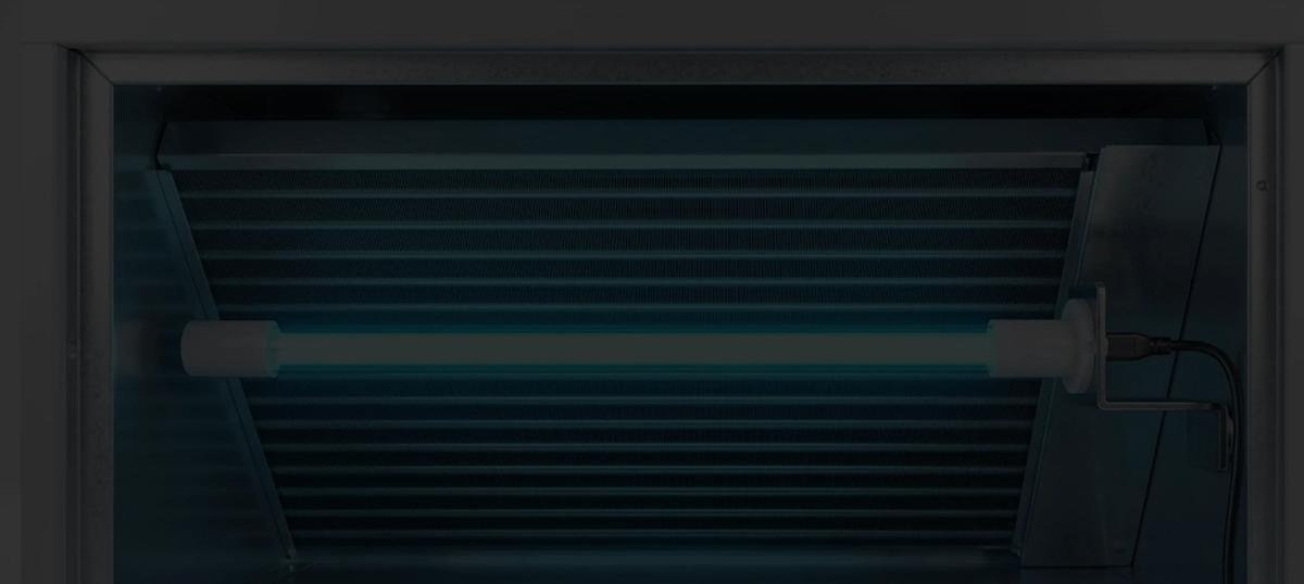
 Installation Guide
 BioShieldUV® MagShield™ (Magnetic) Series Complete Installation Guide
Models covered: SL18 WallPlug | SL36 WallPlug | SL18-HVAC | SL36-HVAC | SL18-HVAC Shield (BioMAG18-HVAC-Shield)
20 min Install Time 8,000 Hours Lamp Life 253.7 nm UV-C WavelengthBefore You Begin: HVAC models must be installed by a licensed HVAC technician or electrical contractor. Installation by anyone other than a qualified professional voids the warranty. All installations must comply with applicable national and local building codes. Read all safety warnings in full before handling any components.
Suitable for Air-Handling Use Dry Locations OnlyQuick Start options
Watch Installation Video:
Jump to a section:
Safety Precautions Where to Install & Mount the Lamp (Part 1) Wiring Installation (Part 2) Reflector Shield (Shield models) Sight Glass & UV Warning Label (Part 3) Product Markings Replacement Instructions Troubleshooting Frequently Asked Questions Follow Safety Precautions closely before beginning installation.Need help with your BioShield UV unit?
Find a certified installer in our professional directory.
Contact UsSafety Instructions
Read every safety section below before touching any component. These warnings apply to all models and all installation environments.
This is the safety-alert symbol
It is used with a signal word — DANGER, WARNING or CAUTION — to call out a hazard to people. DANGER means a hazard that will cause death or serious injury if not avoided. WARNING means a hazard that could cause death or serious injury. CAUTION means a hazard that could cause minor or moderate injury.
SAVE THESE INSTRUCTIONS — keep this guide with the installation.
WARNING UV-C Lamp Safety
This luminaire is designed for use with germicidal lamps and must be installed in compliance with competent technical directions to prevent the user's eye and bare skin from exposure to harmful UV radiation.
Never look at a lit lamp. Check operation only through the sight glass or the indicator light.
Lamp Handling
Handle the UV lamp with gloves at all times. Oils from bare hands reduce UV output and cannot be reversed by cleaning.
If the lamp glass is touched without gloves, wipe the affected area with isopropyl alcohol before powering the unit on.
UV Material Exposure
UV-C light travels in a straight line and degrades many materials in its direct path over time: plastic drain pans, flex duct liner, foam insulation, filter media and exposed wiring.
Keep the lamp cable, its connector, the cable gland and the ballast out of the lamp's direct light. On Shield models the reflector shield does this for the cable; on other models route the cable along the wall directly behind the bracket. Cover any other vulnerable material in the lamp's view with aluminum foil tape. Metal is unaffected.
WARNING Electrical Safety
Turn off power at the breaker or service switch before installing, plugging in or servicing the unit. Some systems have more than one disconnect.
HVAC models connect only to a dedicated 24 VAC transformer. Never add this load to the HVAC unit's own control transformer, and make every splice inside a closed electrical box (Part 2). Do not open the ballast or power-supply housing on either model — there are no user-serviceable parts inside.
Contact with live electrical components can cause serious injury or death.
CAUTION Broken Lamp Hazard
Never touch a broken UV lamp with bare hands.
UV lamps contain a small amount of mercury and may be harmful to skin and eyes if released. If mercury contacts skin, wash the area immediately with mild soap and water and seek medical attention if necessary. Carefully collect broken pieces and dispose of them in accordance with local environmental regulations. Do not use a household vacuum to clean up a broken lamp — sweep the pieces into a sealed plastic bag, ventilate the room, and dispose of them according to your local waste authority's instructions.
WARNING Location Restrictions
Improper installation, adjustment, alteration, service, or maintenance can result in fire or electrical shock.
Installation Restriction
This unit is rated for dry locations only. Install it only on the side where air enters the evaporator coil — never on the coil's discharge side, where condensate blow-off reaches the lamp, and never downstream of electric heat strips or a humidifier. Do not use it in air handlers or furnaces with supplemental electric heat. Do not install this unit outdoors.
Ce luminaire est conçu pour être utilisé avec des lampes germicides et doit être installé en stricte conformité avec les instructions afin d'éviter que les yeux ou la peau de l'utilisateur ne soient exposés aux effets néfastes des rayons UV.
What is in the Box
 A
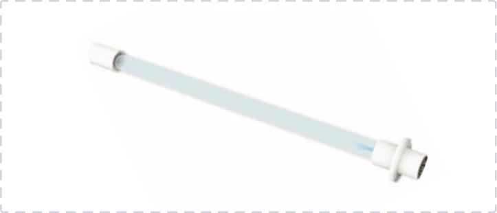
A TruBlu™ UV-C Lamp
UV-C lamp, 253.7 nm
 B
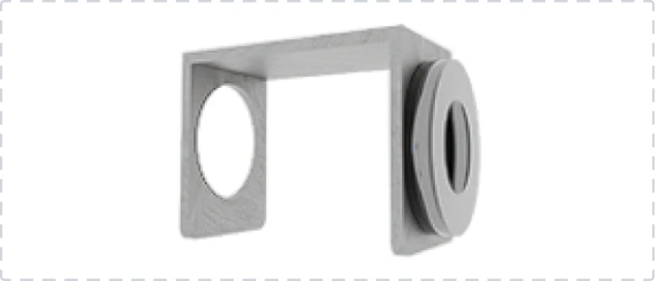
B Magnetic Holder
Steel mounting bracket with lamp holder
 C
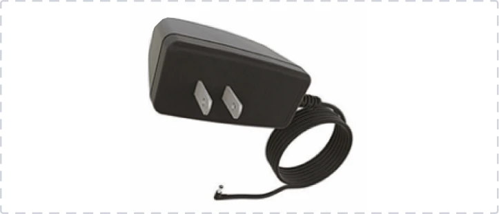
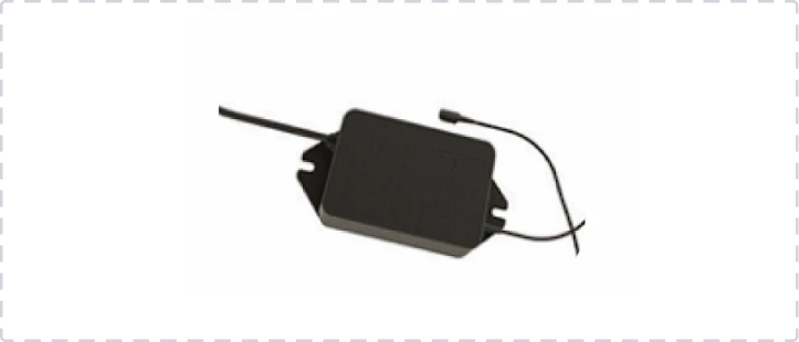
C Power Supply
Wall adapter (WallPlug) or external ballast (HVAC)
 D
D Lamp Cable
4-pin keyed connector cable
 E
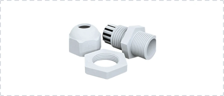
E Cable Gland
Threaded strain relief for duct wall (1″ hole)
 F
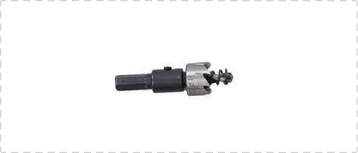
F Step Drill Bit
Creates 1″ cable hole (all models) & ½″ sight glass hole (HVAC)
GUV Warning Label
Goes outside the cabinet at the lamp (all models). HVAC version: its printed circle is the sight-glass drill guide. WallPlug version: no circle, because WallPlug models have no sight glass
 H
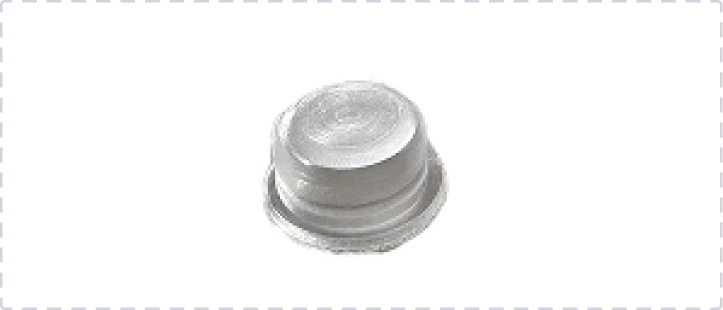
H Viewport
Fixed sight-glass lens, press-fit into the ½″ hole. It is a UV-C barrier and does not open
 I
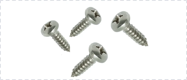
I Self-Tapping Screws ×4
Non-magnetic surface mount & ballast mounting
JTap-In Connectors ×2
For the dedicated 24 VAC transformer leads (HVAC). Use only inside a closed electrical box
KReflector Shield
Shield models only (BioMAG18-HVAC-Shield). Metal reflector that keeps the lamp cable out of direct UV-C. Fitting steps: Reflector Shield
Disclaimer: The information in this guide is provided for educational purposes only. BioShieldUV is a manufacturer of UV-C air treatment devices and does not provide installation services. All installations must be performed in compliance with applicable national and local electrical and mechanical codes. BioShieldUV makes no pesticidal claims. UV-C technology does not replace filtration, ventilation, or other air quality measures. This product is not sold as a medical device and is not for the purpose of diagnosis, treatment, mitigation or prevention of any disease or condition. Results will vary based on system configuration, installation location, and proper maintenance. UV lamps contain small amounts of mercury. Dispose in accordance with local environmental regulations. For recycling information, visit www.lamprecycle.org.
Non-Magnetic Surface Alternative
If the mounting surface is non-ferrous or the magnetic hold is not sufficient, snap the mounting bracket apart by bending it at the joint, remove the magnet, and attach the bracket directly to the duct wall using the included self-tapping screws [I]. Seal any insulation that was disturbed with aluminum foil tape to prevent air leakage.
Part 1: Where to Install & Mount the Lamp
Review the safety precautions before proceeding.
01Find a Suitable Location
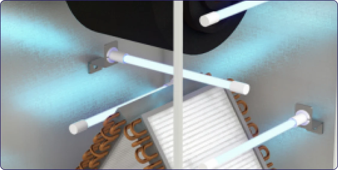
Open the Air Handler Cabinet
- Find the side where air enters the evaporator coil — that is where the lamp goes
- Choose an interior steel panel on that side with a clear, direct line of sight to the coil face
- Position the lamp 12 to 14 inches from the coil
- Aim at the coil face, and at the drain pan wherever it is visible
Swipe the diagram sideways to see all of it →
Mount the lamp where air enters the coil, 12–14 in away. The discharge side of the coil is wet and is not an allowed location.| System Type | Where the lamp goes |
|---|---|
| Upflow (air moves up through the coil) | Below the coil, in the space where air enters it |
| Downflow (air moves down through the coil) | Above the coil, in the space where air enters it |
| Horizontal system | On the side of the coil where air enters, with a clear view of the coil face |
| Heat pump / air handler only | Inside the cabinet on the air-entering side of the coil, aimed at the coil face |
Never mount the lamp on the discharge side of the coil (it is wet from coil blow-off), downstream of electric heat strips, or downstream of a humidifier. This unit is rated for dry locations only.
Clearance and Surface Requirements
The lamp assembly must fit completely inside the cabinet. Make sure there is 18 to 23 inches of open space in the direction the lamp will extend.
The magnetic bracket [B] will only stick to steel. Test the surface with a household magnet before choosing the location. If the magnet does not stick, use the screw-mount method.
Placement Tips
Aim at the center gap between the two angled coil panels, where buildup most commonly collects. Avoid pointing the lamp at filter media, which UV-C degrades with sustained exposure.
02Attach the UV Lamp to the Magnetic Bracket
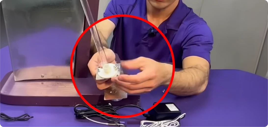
With gloves on, pass the lamp base [A] through the opening in the magnetic mounting bracket [B] and fasten it using the included quick nuts. The lamp should seat firmly against the bracket with no visible gaps.
Shield models: the reflector shield [K] is clamped inside this same joint, so fit it before the quick nuts go down — see Reflector Shield.
03Connect the 4-Pin Lamp Cable
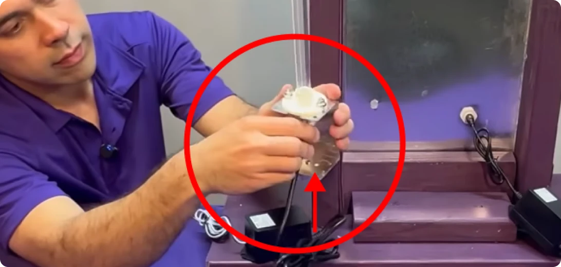
Connect the lamp cable [D] to the 4-pin connector on the UV lamp [A]. Align the keyed tabs with the slots on the lamp, then press firmly until you feel a definitive click.
Do not force the connection. If you encounter resistance, pull back, recheck alignment, and try again.
04Position the Magnetic Bracket
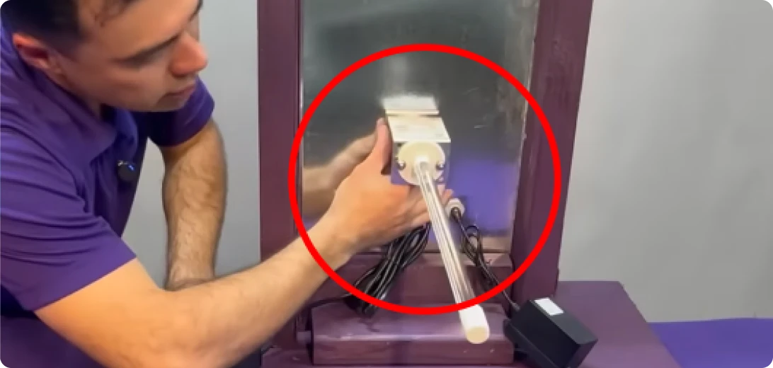
Hold the magnetic base [B] against the chosen steel surface and let it snap into position. Confirm the lamp is aimed at the coil before routing the cable — the magnet lets you reposition freely at this stage.
Shield models: the reflector shield is already clamped into the lampholder joint from step 02. Check its open side still looks at the lamp, and that the cable will run behind it — see Reflector Shield.
After wiring is complete, see How to Confirm the Lamp is Working →
Part 2: Wiring Installation
Confirm your model before proceeding — wiring differs between WallPlug and HVAC models.
01Drill the Cable Exit Hole
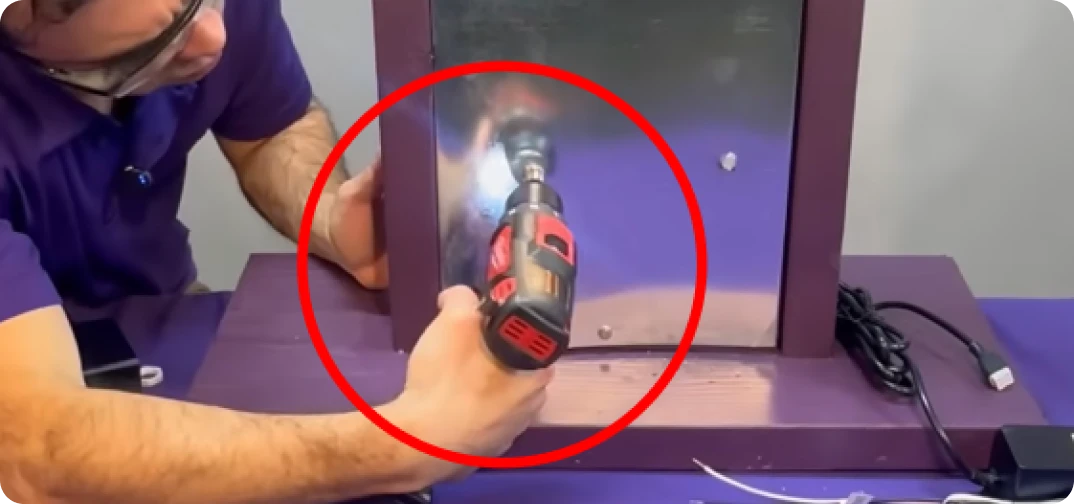
Using the included step drill bit [F], drill a 1" hole through the air handler cabinet wall.
- Place the hole behind the lamp bracket, outside the lamp's direct line of sight
- Position it as low as practical, away from condensate drip paths
- WallPlug models: near an accessible, always-on outlet
Install the Cable Gland
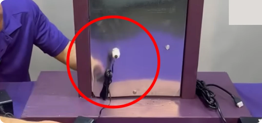
Insert the cable gland [E] into the hole from the outside of the cabinet, thread the locknut on from the inside and tighten until secure.
03Route the Lamp Cable
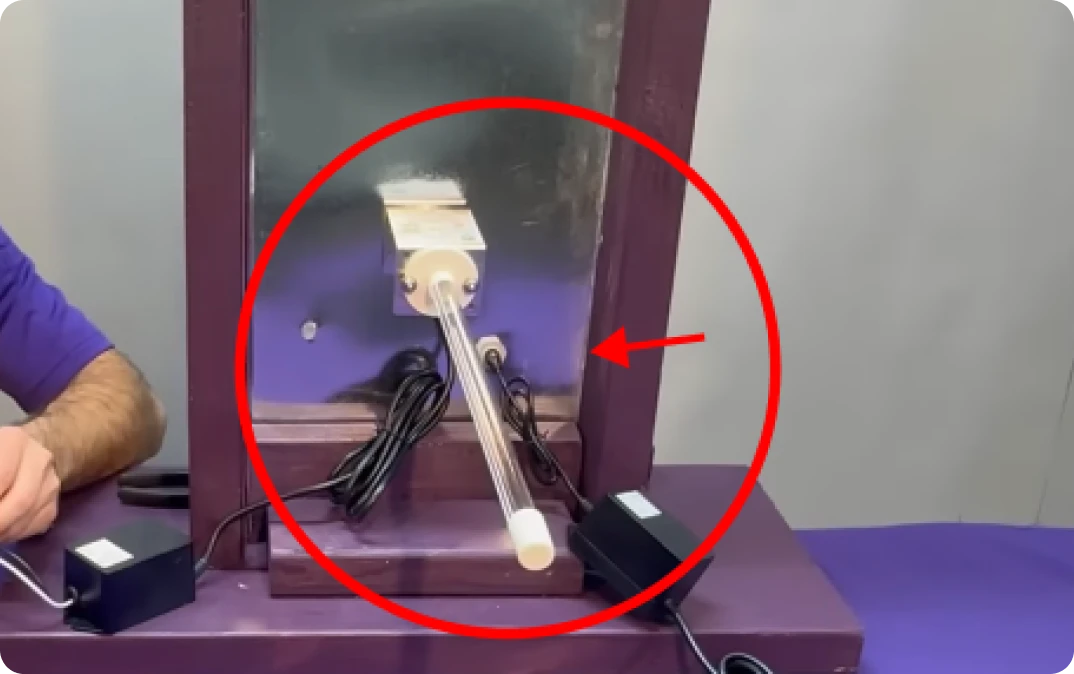
Feed the lamp cable [D] through the gland. Inside the cabinet, run it along the wall directly behind the bracket so no part of it is in the lamp's direct light (Shield models: behind the reflector shield).
Leave a little slack, then tighten the gland nut finger-tight to secure the cable and seal the opening.
Model-Specific Power Connection
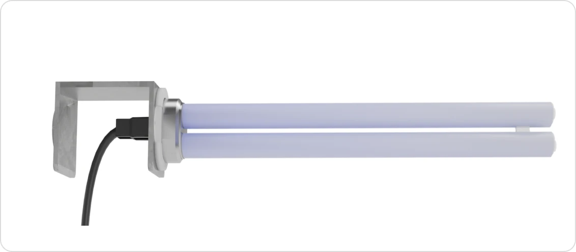
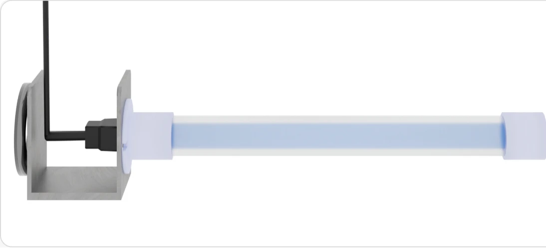
WallPlug Models
SL18-WallPlug and SL36-WallPlug
- Keep the power supply [C] and its connection to the lamp cable outside the cabinet, in a dry, accessible spot. Only the lamp cable passes through the gland.
- Align the square connectors and press firmly until the latch clicks.
- Plug the wall adapter into a nearby always-on outlet (not one controlled by a wall switch).
Important: Connect to constant power — never the blower relay or fan circuit. The lamp is designed to run continuously.
To prevent electric shock, match the wide blade of the plug to the wide slot of the outlet.
Pour éviter les chocs électriques, introduire la lame la plus large de la fiche dans la fente la plus large.
HVAC Models
SL18-HVAC, SL36-HVAC and SL18-HVAC Shield (BioMAG18-HVAC-Shield) — licensed installer only
- Install a dedicated listed Class 2 24 VAC transformer, 40 VA minimum, on a constant-power 120 VAC circuit. Do not add this load to the HVAC unit's own control transformer.
- Make every splice inside a closed electrical box — the transformer's junction box or the air handler's electrical compartment. Use the tap-in connectors [J] only inside that box.
- Mount the ballast [C] in the air handler's electrical / control compartment, behind a panel partition, out of the lamp's line of sight and out of the airstream. Secure it to a flat metal surface with the self-tapping screws [I].
- Connect the ballast output to the lamp cable [D], which enters the lamp compartment through the cable gland [E].
- Wire the 24 VAC feed through the air handler's door or access-panel switch where one exists, in series with the ballast, so opening the panel cuts power to the lamp. If no door switch exists, install a 24 VAC-rated one before energizing the lamp.
Important: Connect to constant power — never the blower relay or fan circuit. The lamp is designed to run continuously.
Swipe the diagram sideways to see all of it →
HVAC models: dedicated 24 VAC transformer, splices inside a closed box, wired through the door/access-panel switch where one exists, ballast in the control compartment out of the lamp's view. Shield modelsReflector Shield
The Shield model — SL18-HVAC Shield, MSKU BioMAG18-HVAC-Shield, UPC 810062155408 — is the 18 W HVAC MagShield with a polished metal reflector shield [K] added. The reflector is a U-channel running the length of the lamp with its open side facing the lamp: the lamp lies inside the trough, so light that would otherwise go into the cabinet wall is turned back toward the coil, and the lamp cable, its 4-pin connector and the cable gland sit behind the channel, out of the lamp's direct UV-C light. It is clamped into the lampholder joint at the base of the lamp, by the two knurled nuts that are already there. Everything else is the standard HVAC installation in Part 1, Part 2 and Part 3 — same placement, same dedicated 24 VAC transformer, same sight glass and warning label, same replacement lamp.
Fitting the reflector shield
- Fit the shield with the lampholder, not after it. The shield is part of the clamped joint at the base of the lamp, so the moment to fit it is Part 1 step 02, when the lamp base [A] goes into the magnetic bracket [B]. If the quick nuts are already down, back them off and lift the lampholder clear of the bracket before you start.
- Drop the shield’s end tab over the two lampholder studs. The tab at the base end of the channel has two holes in it, and they fit the same two threaded studs the lampholder sits on. The bracket’s own centre bolt passes between the two studs — leave it alone, it is not part of this.
- Refit the lampholder over the same two studs, so the shield’s tab is sandwiched between the lampholder and the bracket plate.
- Run the two knurled thumb nuts back down and tighten them finger-tight. Those two nuts are the shield’s only fixing: they clamp lampholder, shield tab and bracket together as one stack. A Shield unit ships with no extra fastener for the shield, and none is needed.
- Check the open side of the channel faces the lamp. The reflector is a U in section — the concave, reflective side looks at the lamp and the lamp lies in the trough; the convex back faces the cabinet wall and the cable. If the trough is facing the wall, the shield is on backwards: slacken the nuts, turn it, and tighten again. The channel must not rest against the lamp glass.
- Check the lamp’s view of the coil is still clear. Sight along the lamp from the coil side. You should see the lamp and the coil face, with the channel behind the lamp and no part of it between the two.
- Now route the cable behind the shield and finish the wiring in Part 2. Then carry on with the sight glass and the UV warning label in Part 3 exactly as for any HVAC model.
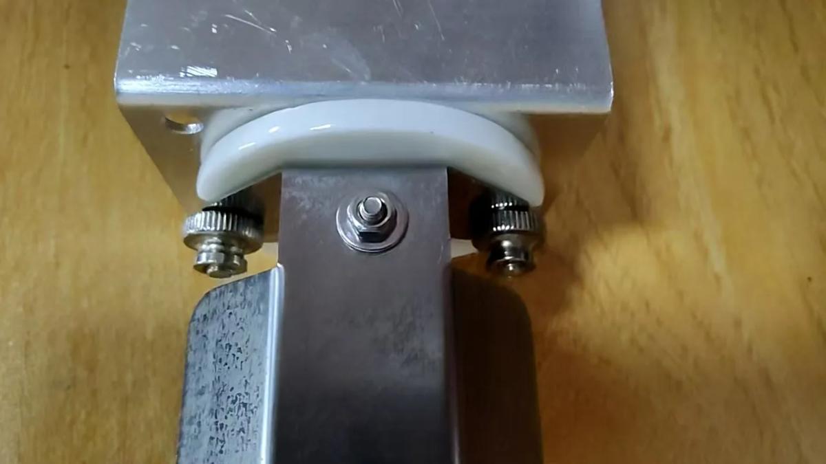 The joint on an actual Shield unit. The shield’s tab is clamped between the lampholder and the bracket plate by the two knurled thumb nuts; the bracket’s own centre bolt sits between them and is not part of the fixing.
 Changing the lamp does not mean removing the shield. The shield is clamped at the base stack and never touches the lamp, so a replacement lamp goes in and out of the channel with the shield left where it is. Follow Replacement Instructions unchanged.
No extra screws, and no drilling. The shield needs no fastener of its own — its two holes drop over the studs already on your unit. The four self-tapping screws listed as part [I] are for mounting the bracket on non-magnetic duct and for the ballast — they are not the shield’s fixing. Do not drill the air handler cabinet to mount the shield, and do not substitute your own screws. If anything about the joint is unclear on the unit in front of you, stop and contact us before going any further.
Swipe the diagram sideways to see all of it →
End view. The lamp lies inside the reflector’s trough, and the cable and gland sit in its shadow. Concept drawing, not to scale — the photograph above is the actual joint.Check before you close the cabinet
- Look along the lamp from the coil side. You should not be able to see the lamp cable, the connector or the gland — the shield hides them.
- Route any spare cable behind the shield, never in front of it.
- Keep the shield’s reflective face — the inside of the channel — clean and free of tape or labels.
- No shield on your model? Run the cable along the wall directly behind the bracket and cover any length still in the lamp's view with aluminum foil tape.
The shield blocks UV-C light only. It does not change the transformer, splice and constant-power rules in Part 2.
Step 01 applies to all models. Steps 02–03 (sight glass) apply to HVAC models only.Part 3: Sight Glass, UV Warning Label & Checking Operation
WallPlug models show lamp status on the power adapter LED: blue means operating, red means service is needed.
HVAC models use a fixed sight glass so you can confirm the lamp is lit from outside the cabinet without opening it. The lens is a permanent UV-C barrier — it does not open.
01Apply the UV Warning Label
Choose a spot on the outside of the cabinet in line with the lamp. Clean and dry the surface, then press the UV warning label [G] firmly into place. On HVAC models, the printed circle at its centre is the drill guide for the next step. WallPlug models have no sight glass: their warning label has no circle, so skip steps 02 and 03 and go straight to Power On and Verify.
Warning — UV Light HazardWARNING — UV LIGHT HAZARD. Harmful to eyes and bare skin. Can cause temporary or permanent loss of vision. Never look at the lamp while lit; check operation only through the sight glass. This air handler is equipped with a UV-C lamp: disconnect power to the UV-C system before servicing any part of the heating and air-conditioning system or removing any access panel.
AVERTISSEMENT — DANGER : LUMIÈRE UV. Nocifs pour la peau nue et les yeux. Peut causer une perte de la vue temporaire ou permanente. Ne jamais regarder la lampe allumée — vérifier son fonctionnement uniquement par le hublot de contrôle. Cet appareil de traitement d'air est équipé d'une lampe UV-C : couper l'alimentation du système UV-C avant d'entretenir toute partie du système de chauffage et de climatisation ou de retirer un panneau d'accès.
Wording printed on the UV warning label [G]
Do not remove or cover this label. It must stay readable for the life of the installation.
02Drill the Sight Glass Hole
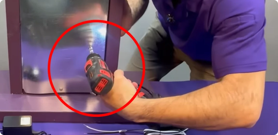
Using the step drill bit [F], drill a 1/2" hole through the centre of the printed circle and the cabinet wall below it.
03Install the Sight Glass Lens
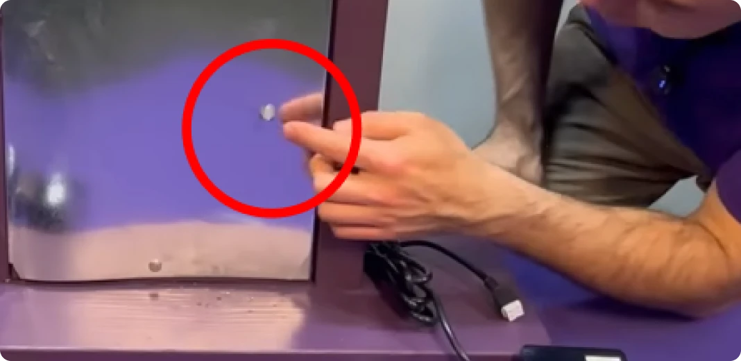
Press the sight glass lens [H] into the hole until it sits flush with the cabinet wall. It press-fits without adhesive and stays in place permanently.
CAUTION: UV LIGHT SOURCE – KEEP PROTECTIVE BARRIER IN PLACE.
ATTENTION : SOURCE DE LUMIÈRE UV – GARDER LA BARRIÈRE DE PROTECTION EN PLACE.
Never operate the unit with the lens missing.
Power On and Verify
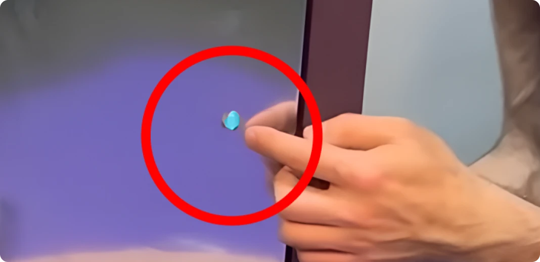
Before restoring power, check that no opening remains through which UV-C light can escape — every panel closed, the sight-glass lens seated, and the cable hole sealed at the gland. Then restore power. A blue glow through the sight glass (HVAC) or a blue LED on the adapter (WallPlug) confirms the lamp is operating. Close the cabinet.
Swipe the diagram sideways to see all of it →
The lens is fixed and flush; the warning label surrounds it on the outside of the cabinet.Indicator Reference
Blue glow through sight glass / Blue LED
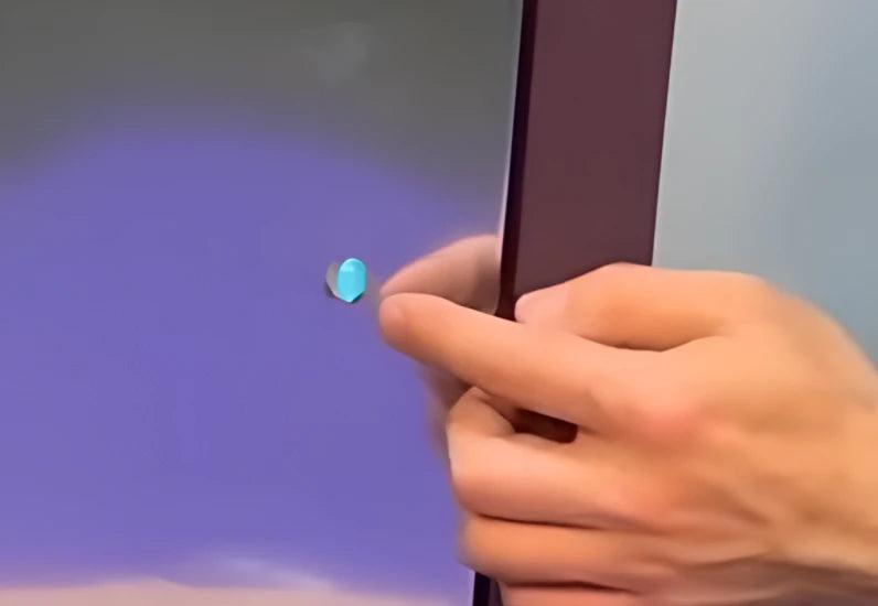
Normal operation. The lamp is on and functioning correctly.
No light
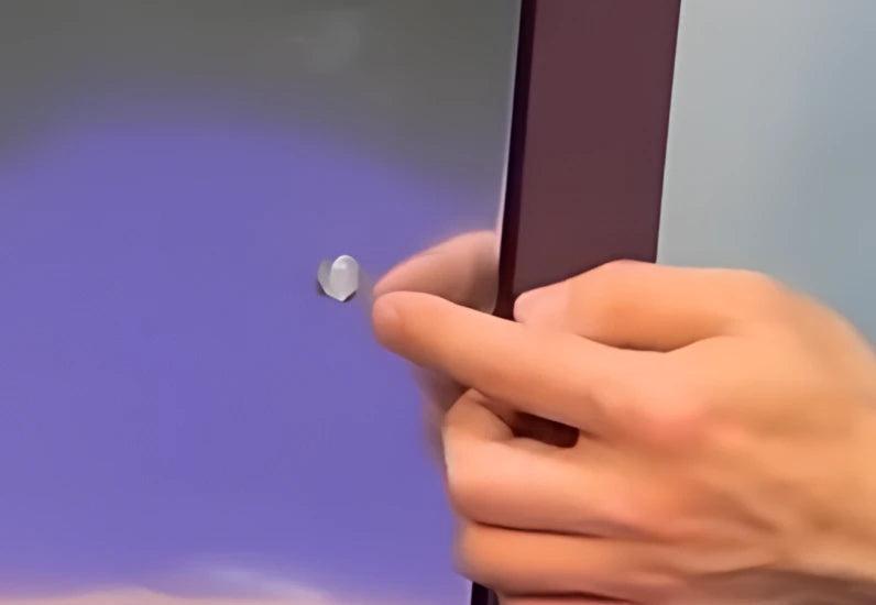
No power is reaching the unit. Check the power connection, transformer output, and circuit breaker.
Red
Lamp at or near end of life, or lamp fault. Reseat the 4-pin connector; if the lamp is over 10 months old, replace it.
Not seeing a blue glow after powering on? Use the troubleshooting table below to diagnose the issue before contacting support.
Jump To TroubleshootingProduct Markings
These safety markings apply to every MagShield unit. They are printed on the unit label together with the model’s ratings — one label per unit. The UV warning goes on the cabinet separately (Part 3).
| English | Français |
|---|---|
| This luminaire is designed for use with germicidal lamps and must be installed in compliance with competent technical directions to prevent the user's eye and bare skin from exposure to harmful UV radiation. | Ce luminaire est conçu pour être utilisé avec des lampes germicides et doit être installé en stricte conformité avec les instructions afin d'éviter que les yeux ou la peau de l'utilisateur ne soient exposés aux effets néfastes des rayons UV. |
| SL18 models: use ballast for 18 watt type UVBulb-MAG18 lamp. | Modèles SL18 : utiliser un ballast convenant à des ampoules de 18 W de type UVBulb-MAG18. |
| SL36 models: use ballast for 36 watt type UVBulb-MAG36 lamp. | Modèles SL36 : utiliser un ballast convenant à des ampoules de 36 W de type UVBulb-MAG36. |
| Use thermally protected ballast for type UVBulb-MAG18 / UVBulb-MAG36 lamps. | Utiliser un ballast protégé thermiquement pour les lampes de type UVBulb-MAG18 / UVBulb-MAG36. |
| WARNING — UV LIGHT HAZARD. Harmful to eyes and bare skin. Can cause temporary or permanent loss of vision. Never look at the lamp while lit; check operation only through the sight glass. This air handler is equipped with a UV-C lamp: disconnect power to the UV-C system before servicing any part of the heating and air-conditioning system or removing any access panel. | AVERTISSEMENT — DANGER : LUMIÈRE UV. Nocifs pour la peau nue et les yeux. Peut causer une perte de la vue temporaire ou permanente. Ne jamais regarder la lampe allumée — vérifier son fonctionnement uniquement par le hublot de contrôle. Cet appareil de traitement d'air est équipé d'une lampe UV-C : couper l'alimentation du système UV-C avant d'entretenir toute partie du système de chauffage et de climatisation ou de retirer un panneau d'accès. |
| SL18-HVAC Shield: assemble part BioSL18W-HVAC only with part ZW17D15W. | Modèle SL18-HVAC Shield : assembler la pièce BioSL18W-HVAC seulement avec la pièce ZW17D15W. |
| SL18-HVAC Shield: 24 volts, 0.7 amps, 18 watts, 60 hertz. Fuse 3T 3.15 A. | Modèle SL18-HVAC Shield : 24 volts, 0,7 ampères, 18 watts, 60 hertz. Fusible 3T 3,15 A. |
| Suitable for air-handling use. | Convient au traitement de l'air. |
| Dry locations only. | Pour emplacements secs seulement. |
| To prevent electric shock, match wide blade of plug to wide slot. (WallPlug models) | Pour éviter les chocs électriques, introduire la lame la plus large de la fiche dans la fente la plus large. |
Replace the lamp only with the TruBlu™ type named above for your model: UVBulb-MAG18 for SL18 models, UVBulb-MAG36 for SL36 models.
Replace Your Bulb Every 10 Months
The TruBlu UV-C lamp is rated for approximately 8,000 hours under continuous operation. Past this point, the lamp will continue to emit a visible blue glow but loses UV-C output. Replace on a 10-month schedule regardless of what the lamp looks like.
Replacement Procedure
- Turn off power to the unit by unplugging the adapter (WallPlug) or disconnecting the transformer (HVAC), and allow the lamp to cool before handling it.
- For HVAC models, confirm through the sight glass that there is no glow before opening the cabinet.
- Open the air handler cabinet. Put on gloves and safety glasses before reaching inside.
- Disconnect the 4-pin connector from the existing lamp, then remove the lamp from the bracket [B].
- Seat the new TruBlu™ replacement lamp in the bracket and reconnect the 4-pin connector until it clicks.
- Check the lamp cable is back out of the lamp’s direct light (behind the reflector shield on the SL18-HVAC Shield / BioMAG18-HVAC-Shield model). Leave the shield in place — it is clamped at the base of the lamp and does not touch the lamp itself, so the new lamp lifts straight out of and back into the channel — see Reflector Shield.
- Close the cabinet and restore power. Confirm the blue LED or blue sight glass glow before leaving the installation.
Use ONLY BioShieldUV TruBlu™ replacement lamps. UVBulb-MAG18 for SL18 models, UVBulb-MAG36 for SL36 models. Other lamp types have not been evaluated with this ballast — use only these lamps.
Never Miss a Replacement with Guardian Club
Guardian Club automatically ships you a replacement lamp every 10 months. Members receive 10% off replacement bulbs, automatic warranty coverage, and hassle-free delivery every cycle.
All replacement bulbs include a 14-day warranty from the date of delivery. Guardian Club members receive extended coverage of up to 6 months from delivery.
Free to join. Ships automatically. Keeps your warranty active.
Join The Guardian Club Order Replacement Bulbs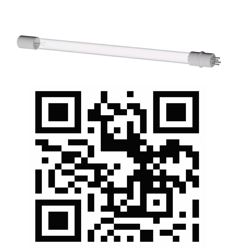 www.BioShieldUV.com/club
 Troubleshooting
| Symptom | Likely Cause | Solution |
|---|---|---|
| Red indicator light | Lamp fault, end of life, or loose 4-pin connector | Reseat the 4-pin connector at both ends. If the lamp is older than 10 months, replace it. If the red light remains after reseating and replacing the lamp, contact support. |
| No indicator light | No power reaching the unit | Check the power outlet, transformer output, and circuit breaker. Confirm the LED switch on the power supply housing is in the left (on) position. |
| No glow visible through sight glass | Lamp not operating or sight glass obstructed | Follow the same diagnostic steps as the red light symptom above. Confirm the sight glass lens [H] is fully seated and the viewing surface is clear. |
| Faint odor on first use | Normal lamp and ballast burn-in period | This is expected behaviour during the initial run and normally clears within 24 to 48 hours of continuous operation. Ventilate the space if the smell persists. For what causes the odor and our UV-C testing, see the odor science page and certifications page. |
| Magnetic bracket will not hold | Non-ferrous (aluminum) mounting surface | Switch to the screw-mount method: snap the bracket apart at the joint, remove the magnet, and fasten the bracket directly to the duct wall with the included self-tapping screws [I]. |
| Condensation at the cable entry point | Cable gland not fully sealed | Re-tighten the locknut on the cable gland [E]. If the issue continues, apply aluminum foil tape around the full perimeter of the penetration. |
UV-C Lamp Disposal
UV-C lamps contain a small amount of mercury and must be disposed of in accordance with local environmental regulations. Do not place used lamps in standard household waste unless your local waste management authority explicitly permits it.
Visit www.lamprecycle.org to find mercury lamp recycling locations near you, or www.earth911.com to locate your local or state waste management program.
Many hardware and home improvement retailers that sell UV or fluorescent bulbs also accept used bulbs for drop-off recycling at no charge. If no recycling option is available and local regulations allow, seal the lamp in a plastic bag before placing it in household waste collection.

Frequently Asked Questions
Do I need a professional installer? WallPlug models are designed for homeowner installation. HVAC models connect to a dedicated 24 VAC transformer and must be installed by a licensed HVAC technician or electrician. Installation by an unlicensed individual on an HVAC model voids the warranty. Where exactly should I install the UV lamp? On the side where air enters the evaporator coil, 12–14 inches from the coil, with a clear view of the coil face — see the placement table in Part 1. Can I mount the lamp after the coil, on the supply side? No. The discharge side of the coil is wet from condensate blow-off, and this unit is rated for dry locations only. Mount it where air enters the coil. Why can't I power it from the HVAC unit's existing transformer? The HVAC unit's control transformer is sized for its own load. Adding the lamp can overload it and affect its safety rating. Use a dedicated 24 VAC transformer, 40 VA minimum, and make every splice inside a closed electrical box. Can I wire the unit to run only when the HVAC fan runs? No. HVAC models must be wired to constant 24 VAC power, not the blower relay. The lamp is designed to run continuously. WallPlug models run continuously from an always-on outlet. What does the reflector shield do? On Shield models it keeps the lamp cable, connector and cable gland out of the lamp's direct UV-C light and reflects that light toward the coil. See Reflector Shield. I bought the Shield model. Is the installation different? No. BioMAG18-HVAC-Shield is the 18 W HVAC MagShield with the reflector shield added, so it is the same installation as SL18-HVAC — same placement, same dedicated 24 VAC transformer, same sight glass and warning label — plus one extra job: fit the shield after you mount the bracket and before you route the cable. See Reflector Shield. The lamp has a visible blue glow. Is UV-C actually working? A blue glow confirms the lamp is powered, but not that UV-C output is still at full strength — output fades well before the lamp goes dark. That is why replacement is on a 10-month schedule regardless of appearance. My unit is showing a red light. What do I do? A red indicator means the lamp is at or near end of life. Replace it with the genuine TruBlu™ lamp for your model to restore full UV-C output. Will UV-C damage plastic or rubber components inside my system? Prolonged direct exposure can degrade some plastics, rubber and wire insulation. Keep non-metallic parts — including the lamp cable — out of the direct beam, and inspect nearby materials periodically. Can I install this on non-metallic ductwork? Yes. Use the included self-tapping screws to mount the bracket instead of the magnet. See the Non-Magnetic Surface Alternative. What if my HVAC is a communicating system such as Nest or Ecobee? It works alongside it. HVAC models run from their own dedicated 24 VAC transformer on constant power and do not communicate with the thermostat. Is the MagShield ETL listed? Not yet. Certification of the complete unit with Intertek is in progress. We will show the ETL mark only once the listing has been issued. See our certifications page for current status. The unit smells strange on first use. Is that normal? A faint smell can occur when the lamp first energizes and should fade within 24 to 48 hours. Ventilate the space; a persistent strong smell warrants a check of placement. See our odor science page for more. How do I know when to replace the bulb? Every 10 months (about 8,000 hours). UV-C output fades before the lamp goes dark, so replace on schedule. The Guardian Club ships replacements automatically.Take replacement off your to-do list entirely. Guardian Club members receive automatic delivery on the right schedule. [Join for free →]
Need Help?
 Text or Call: +1 (307) 364 0340 - available in the US and Canada Email: [email protected] Hours: Monday to Friday, 9 am to 6 pm PST